Page 1 of 1
AB763 cut 68k resistor
PostPosted:Fri Nov 21, 2014 12:36 pm
by tatittle
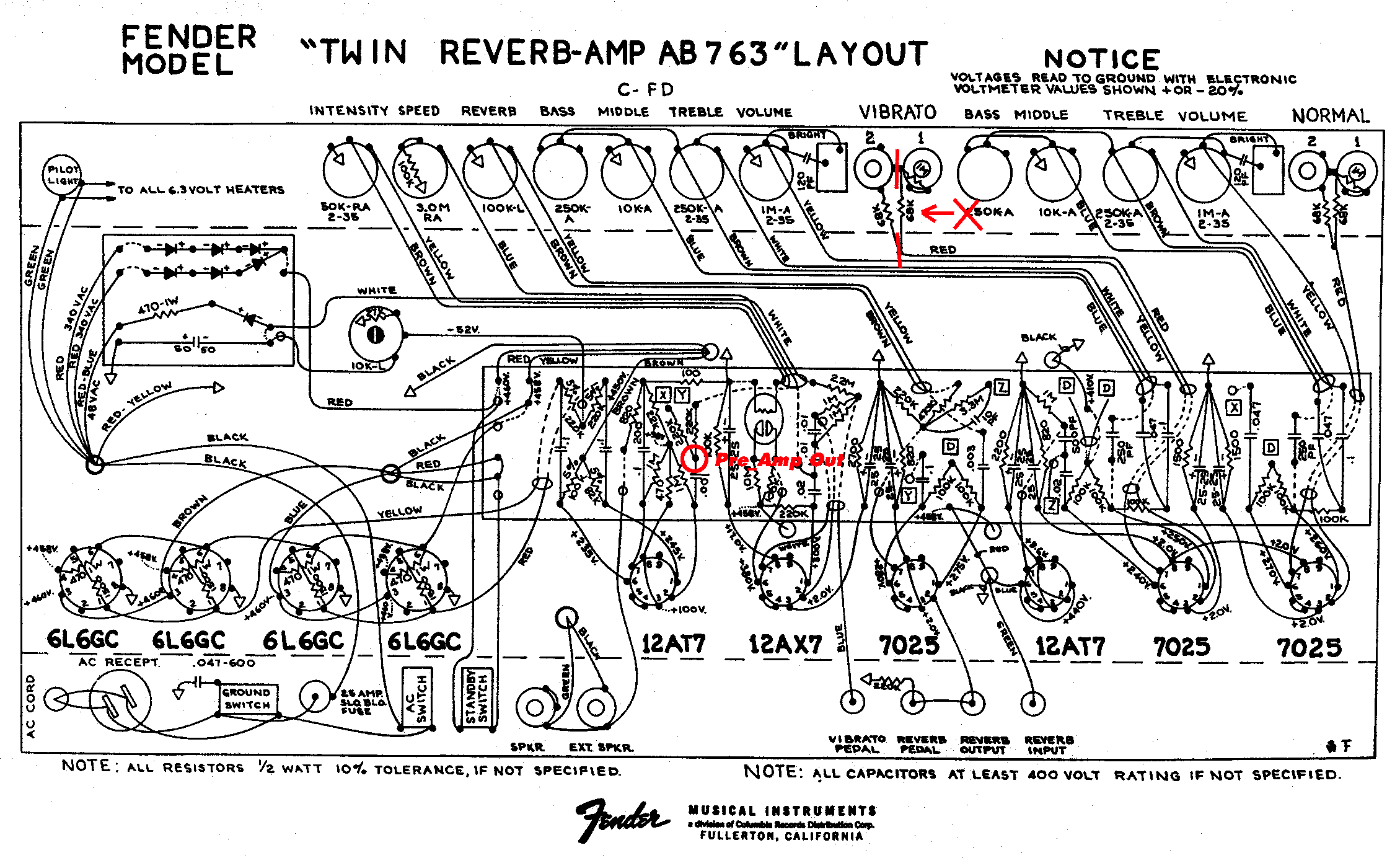
http://www.dozin.com/gear/preamp/ab763preampout.jpeg
Anyone cut their 68k resistor like this diagram shows? Doing it per diagram would disable the #2 input right?
Ive read the resistor is noisy. Anybody swear by this particular mod.?
Re: AB763 cut 68k resistor
PostPosted:Fri Nov 21, 2014 3:38 pm
by Searing75
You can cut out the resistor and still hook up to both jacks, so they both work. I prefer it without the resistor.
Chris
Re: AB763 cut 68k resistor
PostPosted:Fri Nov 21, 2014 5:59 pm
by softmachine72
I found this about the 68k input resistors
Those resistors are not just put on the control grid for signal level
attenuation purposes; rather, they also act as a very high frequency
low-pass filter in conjunction with the input capacitance of the triode
(which is a sum of the grid-to-cathode capacitance and the Miller
capacitance).
This low-pass filter does a couple of things: (1) it helps prevent high
frequency parasitic oscillation in the tube itself; (2) it helps prevent
radio frequencies from getting into the input stage, where they can be
rectified and lowpass filtered (AM detection) and become audible at the
amplifier output; and (3) it can limit grid current when the tube is
driven into the positive grid region.
You will notice on two-input amps, such as Fenders, when you plug into
the low-level input, the 1MEG grid resistor is shorted out and the two
68K resistors act as an attenuator to cut the input signal in half. The
downside of this is that the input impedance drops from approximately
1MEG down to approximately 136K, which is a rather heavy load for a high
impedance guitar pickup.
If the resistor is connected in series with the input jack and before
the 1MEG grid resistor, there is a small attenuation of the input signal
(0.94 times). If the low-level input attenuation is not necessary, the
resistor is best placed after the 1MEG grid resistor and should be
soldered directly to the grid pin instead of back at the input jack.
This will be the best position for RF and parasitic oscillation
attenuation.
Bottom line: leave it on there.
Re: AB763 cut 68k resistor
PostPosted:Fri Nov 21, 2014 8:14 pm
by Searing75
Oh yeah! Actually, I moved that resistor from its original location and soldered it directly to pin 2 (I believe) of V2. For the exact reason soft machine noted. Been a while. I forget what mods I have done, undone, and whatnot. This was on my Twin. I wonder what Brad does on the SMS? I will have to peak under the hood.
Re: AB763 cut 68k resistor
PostPosted:Fri Nov 21, 2014 8:18 pm
by PHersh
I have asked two tube amp EEs in recent years about clipping the input resistors on Blackface amps and both gave me the same reasons NOT to do it as Softmachine72 cites above. I too recall reading that those resistors were removed from Jerry's Twin Reverb preamps as they were said to cause hiss.
In my FYD "Jerry" preamp, the resistors are present on the board, with leads connecting to the input jacks.
Re: AB763 cut 68k resistor
PostPosted:Sat Nov 22, 2014 12:13 am
by SarnoMusicSolutions
Searing75 wrote:...I wonder what Brad does on the SMS? I will have to peak under the hood.
The SMS doesn't have the 68k resistors because they're also there as mixing resistors if two guitars were sharing the channel. Since the SMS CL is just a single input, none of that was an issue. So I have no need to do any of that stuff. Softmachine72 made a bunch of great points about the good reasons to have some of that series resistance on the way to the tube's grid (input). So with a combination of going for that Alembic/Garcia style input mod where there is not any series resistance at the input jack mixed with adding just a bit, just enough series resistance to be beneficial. These "grid stopper" resistors actually do best when right at the pin of the tube socket, so that's where I put it.
On a Fender amp, you get about 34kOhms of series resistance at the jack. That 34k is a slightly audible low-pass-filter that reduces some of the high frequency response. In the SMS I put a grid stopper right at the tube socket that's a much smaller value, big enough to help keep out radio interference and keep the tube stable at high frequencies, but all that action. is well above the audible band. This way it behaves like Garcia's with that very open sound on top but keeps out some of the nasty stuff.
Brad
www.sarnomusicsolutions.com
Re: AB763 cut 68k resistor
PostPosted:Sat Nov 22, 2014 3:11 pm
by Rick Turner
Two comments...
When was the last time you or anyone you saw or heard plugged two instruments into one channel of a Fender-style amp? That passive mixing stage is just unnecessary and it does add noise. But...the original Alembic mod was to use a switching jack on the second input of each channel to allow for passive mixing. The 68 K series resistor was still there, but as I recall, Ron always tried for the lowest noise resistors possible.
Don't forget, that for much of Garcia's later career, he had a buffered output from his guitar, so the source to load was a lot different from "normal" hi Z guitar to amp matching.
Re: AB763 cut 68k resistor
PostPosted:Sun Nov 23, 2014 10:43 am
by TI4-1009
Rick Turner wrote:When was the last time you or anyone you saw or heard plugged two instruments into one channel of a Fender-style amp? .
In my 60's high school garage band. All the time!

Re: AB763 cut 68k resistor
PostPosted:Sun May 27, 2018 11:47 am
by Jerms
Hi. I see this is an old thread but I have a question regarding this issue exactly. I came across this:
http://torresengineering.stores.yahoo.n ... uitar.html
My question is, if you do move the two resistors to right before pin 2 of the preamp tube, as I have done on my stock ‘73 TR (wired together in parallel), does this mean only input jack 1 is usable? My understanding is, that with the switching jack setup described, when jack 2 is used the 1M grid load resistor is out of the circuit and there is no 68k resistor there to act as such. So what I’ve done is simply tape over jack 2 so I don’t accidentally plug in there. Is there a way to keep the 1M resistor in the circuit when using jack 2? Or could I give jack 2 it’s own 1M resistor? I realize the result would just be two identical jacks; I just don’t like having the tape there. I guess I could just disconnect jack 2 entirely, but that seems a little sloppy also.
I do think the amp sounds noticeably better with the resistors moved. At first I just took them out completely. It sounded great with a stock Squier Tele, but with my Troy Post (TPC-1, Super IIs, coil tap on, OBEL bypassed) it was way noisy and a little over the top on the bright side. After putting the resistors before the preamp tube, the noise was back to the normal level and the tone seemed brighter than with the resistors on the jack but well balanced.