Bumping with Wild Eye's question from
another thread, which probably belongs here:
WildEye wrote:Hey Red Eye,
Can you give some more detail about your OBEL volume pot? I talked about it here ( forum/viewtopic.php?f=309&t=12439 ) plus there were a couple other posts where people had differing results...
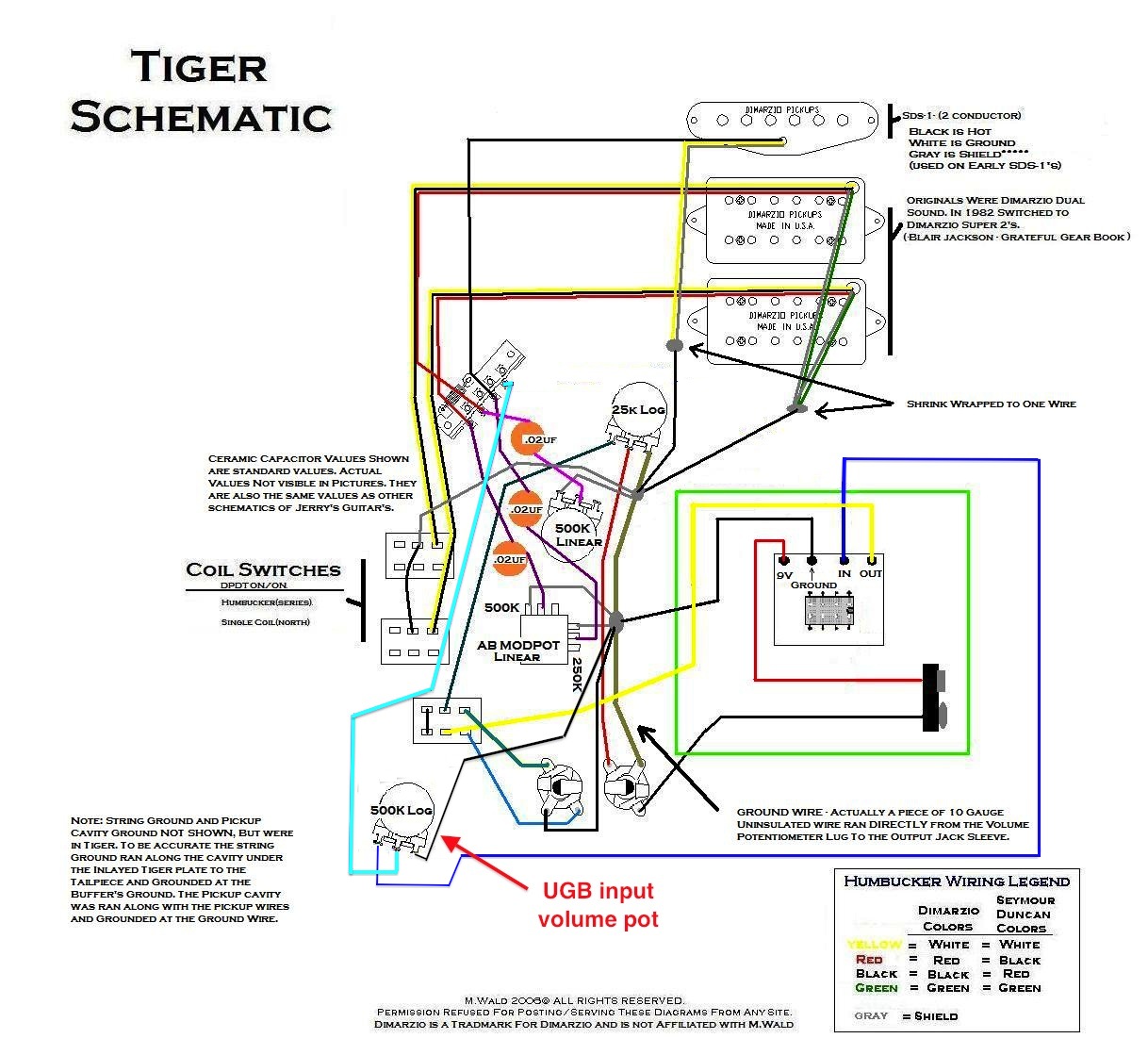
Sure, WildEye. I took what I thought was the direct route, just a 25k log pot wired into the send leg of the OBEL circuit, between the OBEL selector switch and the OBEL jack. Here's a quick, crude diagram of the pot, added to MIke Wald's familiar Tiger schematic (and with full credit/thanks to Mike for making such a detailed drawing, which helped me greatly when I did my OBEL conversion last year):
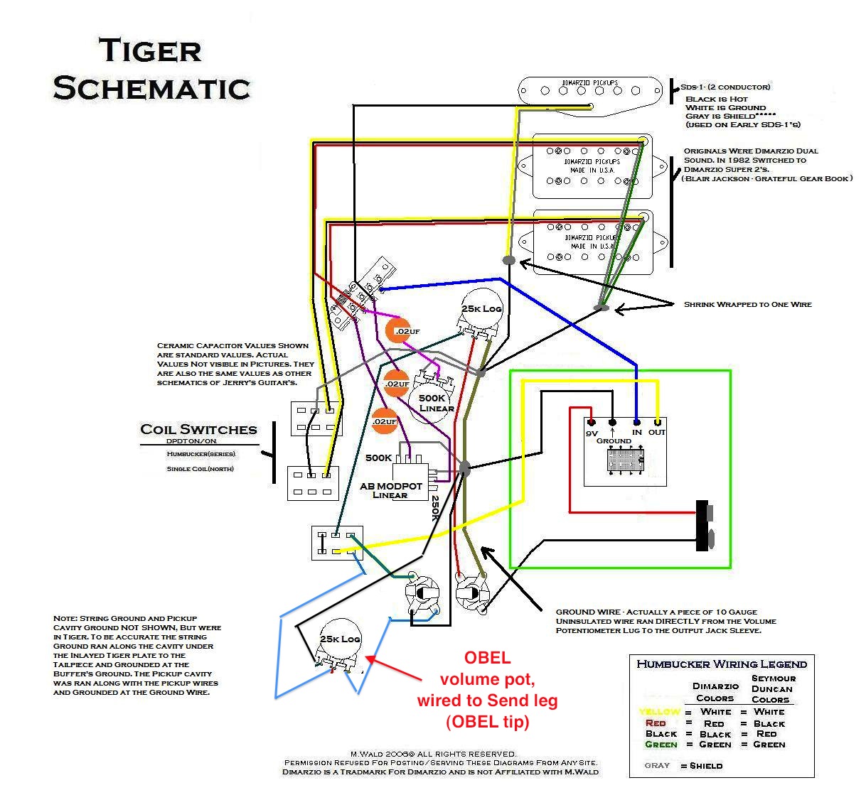
Given how the frames on this site tend to cut off large images, you might want to right click and Save As... to your local drive to see the whole thing.
I thought I was implementing the same solution brad mentioned
here:
I've done it a few times and even have it on a guitar currently. You can simply add a "normal" volume pot in your guitar wired up before the buffer. When the pot is on 10, it's essentially like it's not there, full signal to the buffer, and you have a normal OBEL guitar. If you turn down that volume knob, you still have the buffer right there to handle the loop and OBEL functions, but you've turned down the guitar level to hit your overdrive pedal more softly to "clean" it up a bit. You still need the main OBEL master volume pot as usual. It works great.
Brad
Of course, in re-reading that just now I see that I did NOT follow his method (a regular guitar pot controlling buffer input signal strength) and am instead controlling the buffer output volume with a 25k log pot, and then further cutting the buffer output volume with another 25k log pot when it leaves my guitar and feeds my amp. Am I killing my tone by doing it that way? It doesn't sound bad, but then it's late where I am so I can't really crank it above bedroom levels at the moment. Maybe I'd get better tone if I did it the way he suggested and had one signal attenuation before the buffer and one after, instead of none and two? Any thoughts? I feel a little foolish at the moment, but it's nothing that a little solder and a part swap won't fix